You’re playing the latest Call of Mario: Deathduty Battleyard on your perfect gaming PC. You’re looking at a beautiful 4K ultra widescreen monitor, admiring the glorious scenery and intricate detail. Ever wondered just how those graphics got there? Curious about what the game made your PC do to make them?
Welcome to our 101 in 3D game rendering: a beginner’s guide to how one basic frame of gaming goodness is made.
Every year hundreds of new games are released around the globe – some are designed for mobile phones, some for consoles, some for PCs. The range of formats and genres covered is just as comprehensive, but there is one type that is possibly explored by game developers more than any other kind: 3D.
The first ever of its ilk is somewhat open to debate and a quick scan of the Guinness World Records database produces various answers. We could pick Knight Lore by Ultimate, launched in 1984, as a worthy starter but the images created in that game were strictly speaking 2D – no part of the information used is ever truly 3 dimensional.
So if we’re going to understand how a 3D game of today makes its images, we need a different starting example: Winning Run by Namco, around 1988. It was perhaps the first of its kind to work out everything in 3 dimensions from the start, using techniques that aren’t a million miles away from what’s going on now. Of course, any game over 30 years old isn’t going to truly be the same as, say, Codemasters F1 2018, but the basic scheme of doing it all isn’t vastly different.
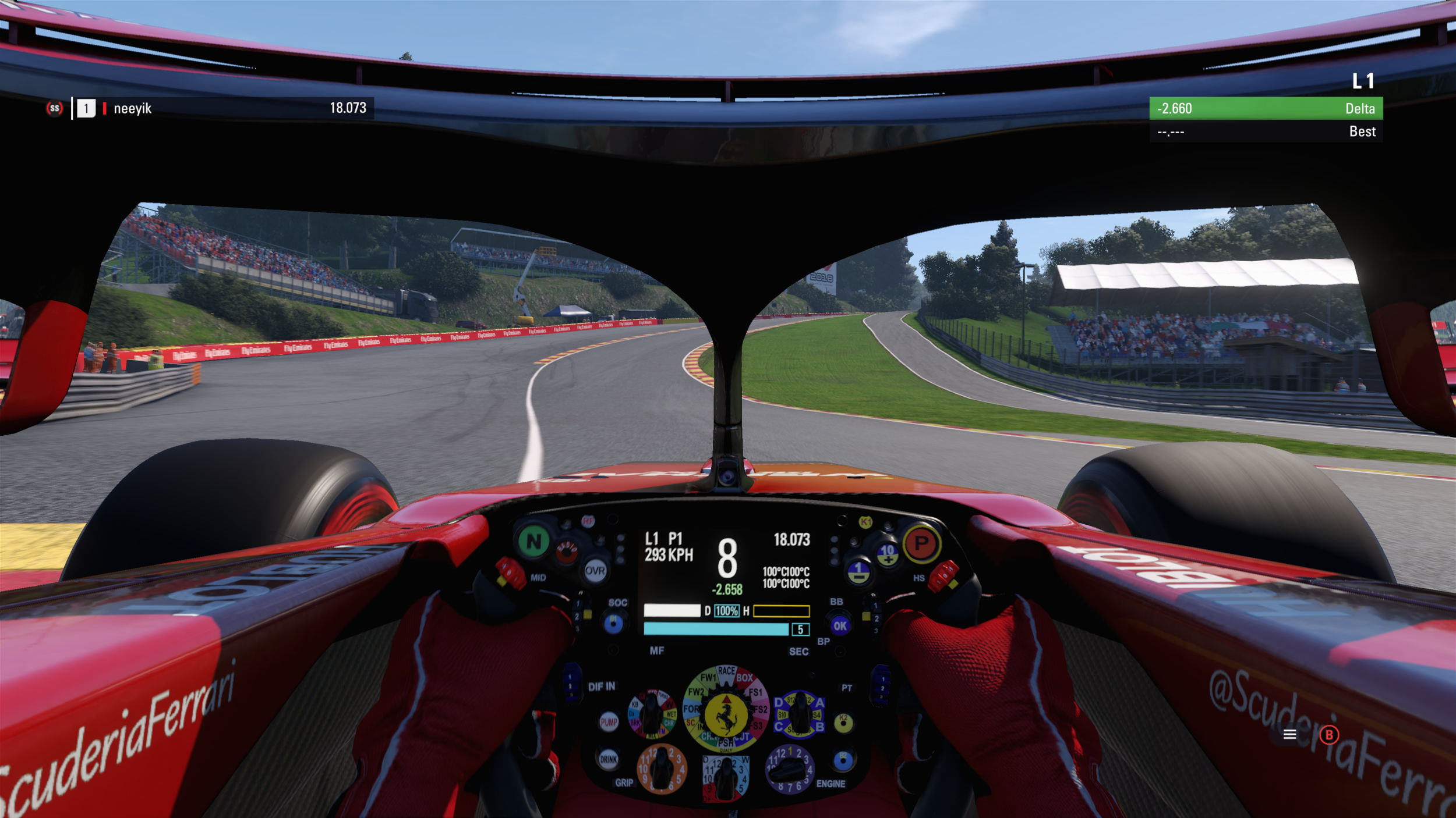
In this article, we’ll walk through the process a 3D game takes to produce a basic image for a monitor or TV to display. We’ll start with the end result and ask ourselves: “What am I looking at?”
From there, we’ll analyze each step performed to get that picture we see. Along the way, we’ll cover neat things like vertices and pixels, textures and passes, buffers and shading, as well as software and instructions. We’ll also take a look at where the graphics card fits into all of this and why it’s needed. With this 101, you’ll look at your games and PC in a new light, and appreciate those graphics with a little more admiration.
 TechSpot’s 3D Game Rendering Series
You’re playing the latest games at beautiful 4K ultra res. Did you ever stop to wonder just how those graphics got there? Welcome to our 3D Game Rendering 101: A beginner’s guide to how one basic frame of gaming goodness is made.
Part 0: 3D Game Rendering 101
The Making of Graphics Explained
Part 1: 3D Game Rendering: Vertex Processing
A Deeper Dive Into the World of 3D Graphics
Part 2: 3D Game Rendering: Rasterization and Ray Tracing
From 3D to Flat 2D, POV and Lighting
Part 3: 3D Game Rendering: Texturing
Bilinear, Trilinear, Anisotropic Filtering, Bump Mapping, More
Part 4: 3D Game Rendering: Lighting and Shadows
The Math of Lighting, SSR, Ambient Occlusion, Shadow Mapping
Part 5: 3D Game Rendering: Anti-Aliasing
SSAA, MSAA, FXAA, TAA, and Others
Aspects of a frame: pixels and colors
Let’s fire up a 3D game, so we have something to start with, and for no reason other than it’s probably the most meme-worthy PC game of all time… we’ll use Crytek’s 2007 release Crysis.
In the image below, we’re looking a camera shot of the monitor displaying the game.
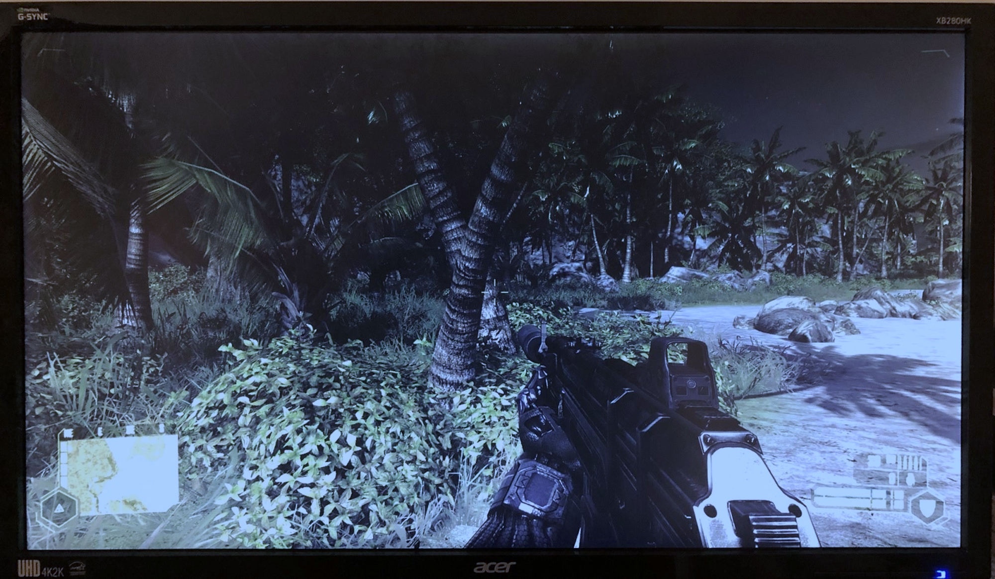
This picture is typically called a frame, but what exactly is it that we’re looking at? Well, by using a camera with a macro lens, rather than an in-game screenshot, we can do a spot of CSI: TechSpot and demand someone enhances it!
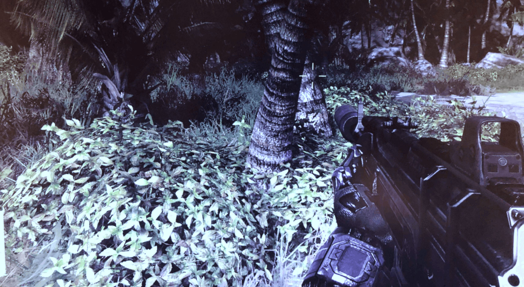
Unfortunately screen glare and background lighting is getting in the way of the image detail, but if we enhance it just a bit more…

We can see that the frame on the monitor is made up of a grid of individually colored elements and if we look really close, the blocks themselves are built out of 3 smaller bits. Each triplet is called a pixel (short for picture element) and the majority of monitors paint them using three colors: red, green, and blue (aka RGB). For every new frame displayed by the monitor, a list of thousands, if not millions, of RGB values need to be worked out and stored in a portion of memory that the monitor can access. Such blocks of memory are called buffers, so naturally the monitor is given the contents of something known as a frame buffer.
That’s actually the end point that we’re starting with, so now we need to head to the beginning and go through the process to get there. The name rendering is often used to describe this but the reality is that it’s a long list of linked but separate stages, that are quite different to each other, in terms of what happens. Think of it as being like being a chef and making a meal worthy of a Michelin star restaurant: the end result is a plate of tasty food, but much needs to be done before you can tuck in. And just like with cooking, rendering needs some basic ingredients.
The building blocks needed: models and textures
The fundamental building blocks to any 3D game are the visual assets that will populate the world to be rendered. Movies, TV shows, theatre productions and the like, all need actors, costumes, props, backdrops, lights – the list is pretty big.
3D games are no different and everything seen in a generated frame will have been designed by artists and modellers. To help visualize this, let’s go old-school and take a look at a model from id Software’s Quake II:
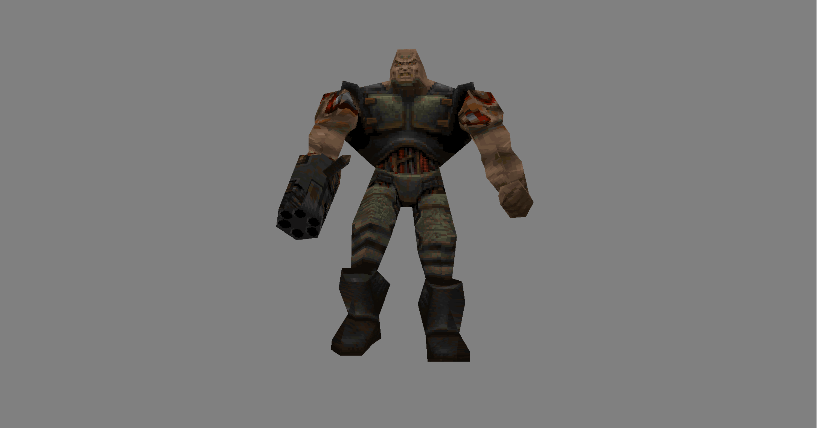
Launched over 25 years ago, Quake II was a technological tour de force, although it’s fair to say that, like any 3D game two decades old, the models look somewhat blocky. But this allows us to more easily see what this asset is made from.
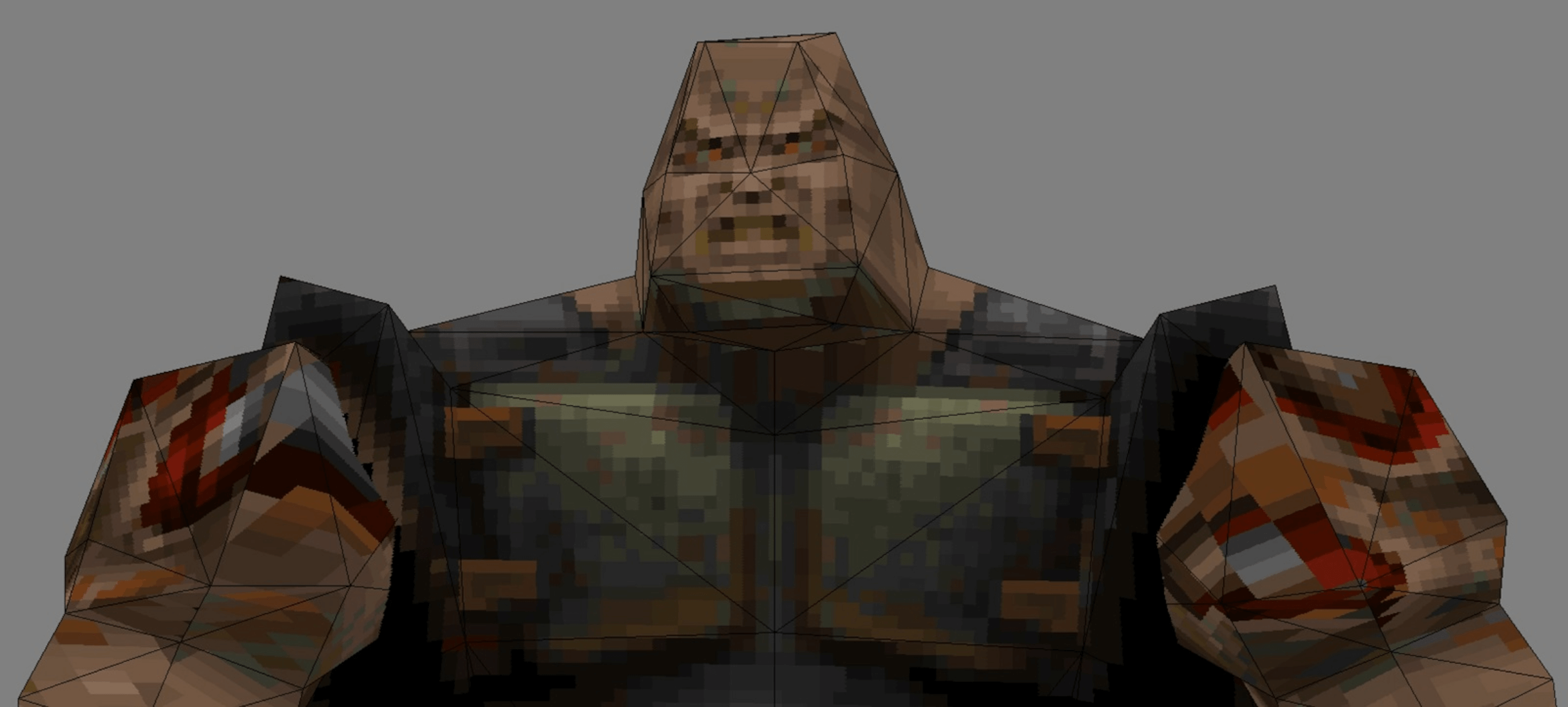
In the first image, we can see that the chunky fella is built out connected triangles – the corners of each are called vertices or vertex for one of them. Each vertex acts as a point in space, so will have at least 3 numbers to describe it, namely x,y,z-coordinates. However, a 3D game needs more than this, and every vertex will have some additional values, such as the color of the vertex, the direction it’s facing in (yes, points can’t actually face anywhere… just roll with it!), how shiny it is, whether it is translucent or not, and so on.
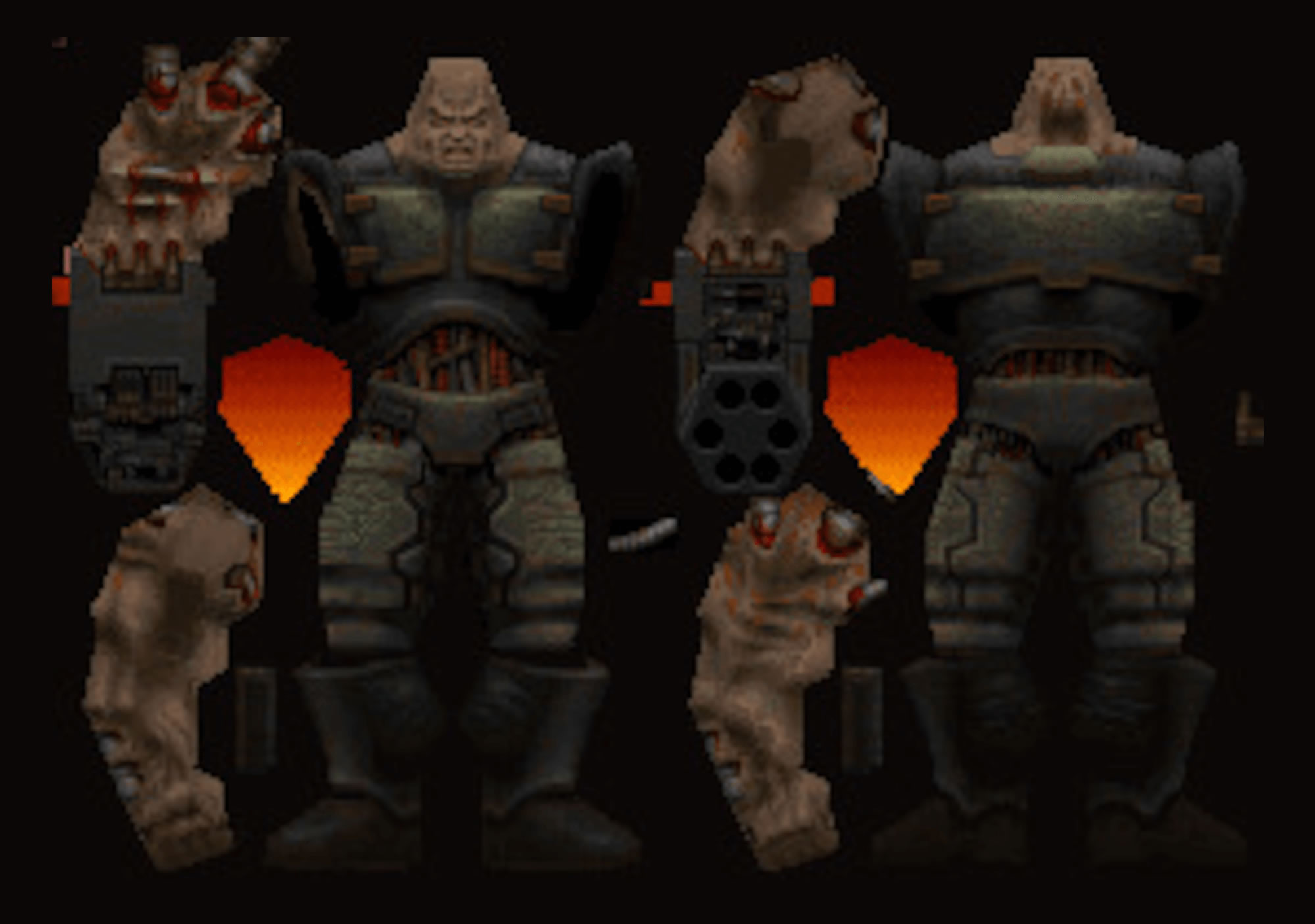
One specific set of values that vertices always have are to do with texture maps. These are a picture of the ‘clothes’ the model has to wear, but since it is a flat image, the map has to contain a view for every possible direction we may end up looking at the model from. In our Quake II example, we can see that it is just a pretty basic approach: front, back, and sides (of the arms).
A modern 3D game will actually have multiple texture maps for the models, each packed full of detail, with no wasted blank space in them; some of the maps won’t look like materials or feature, but instead provide information about how light will bounce off the surface. Each vertex will have a set of coordinates in the model’s associated texture map, so that it can be ‘stitched’ on the vertex – this means that if the vertex is ever moved, the texture moves with it.
So in a 3D rendered world, everything seen will start as a collection of vertices and texture maps. They are collated into memory buffers that link together – a vertex buffer contains the information about the vertices; an index buffer tells us how the vertices connect to form shapes; a resource buffer contains the textures and portions of memory set aside to be used later in the rendering process; a command buffer the list of instructions of what to do with it all.
This all forms the required framework that will be used to create the final grid of colored pixels. For some games, it can be a huge amount of data because it would be very slow to recreate the buffers for every new frame. Games either store all of the information needed, to form the entire world that could potentially be viewed, in the buffers or store enough to cover a wide range of views, and then update it as required. For example, a racing game like F1 2018 will have everything in one large collection of buffers, whereas an open world game, such as Bethesda’s Skyrim, will move data in and out of the buffers, as the camera moves across the world.
Setting out the scene: The vertex stage
With all the visual information to hand, a game will then commence the process to get it visually displayed. To begin with, the scene starts in a default position, with models, lights, etc, all positioned in a basic manner. This would be frame ‘zero’ – the starting point of the graphics and often isn’t displayed, just processed to get things going.
To help demonstrate what is going on with the first stage of the rendering process, we’ll use an online tool at the Real-Time Rendering website. Let’s open up with a very basic ‘game’: one cuboid on the ground.
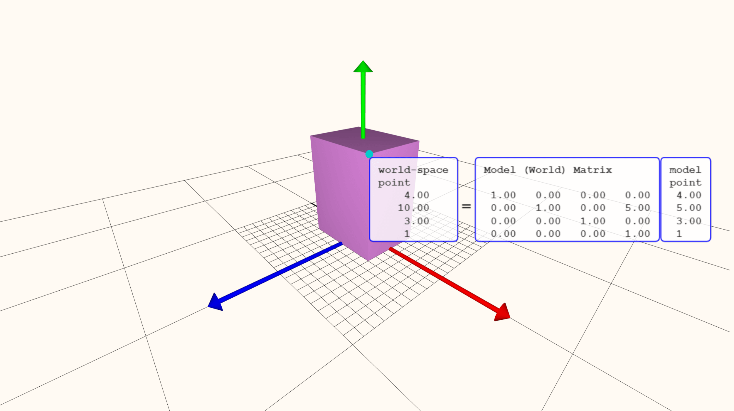
This particular shape contains 8 vertices, each one described via a list of numbers, and between them they make a model comprising 12 triangles. One triangle or even one whole object is known as a primitive. As these primitives are moved, rotated, and scaled, the numbers are run through a sequence of math operations and update accordingly.
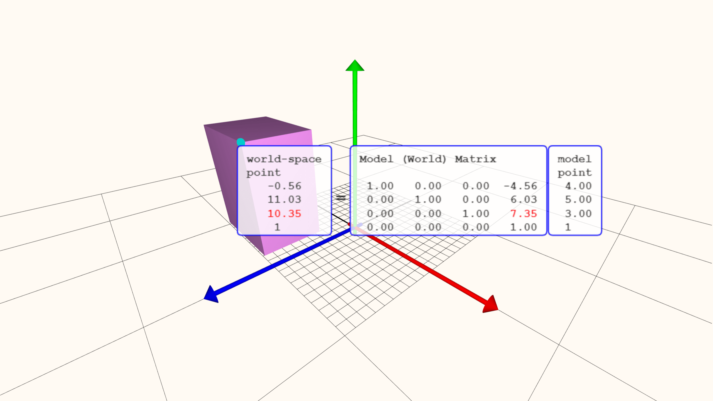
Note that the model’s point numbers haven’t changed, just the values that indicate where it is in the world. Covering the math involved is beyond the scope of this 101, but the important part of this process is that it’s all about moving everything to where it needs to be first. Then, it’s time for a spot of coloring.

Let’s use a different model, with more than 10 times the amount of vertices the previous cuboid had. The most basic type of color processing takes the colour of each vertex and then calculates how the surface of surface changes between them; this is known as interpolation.
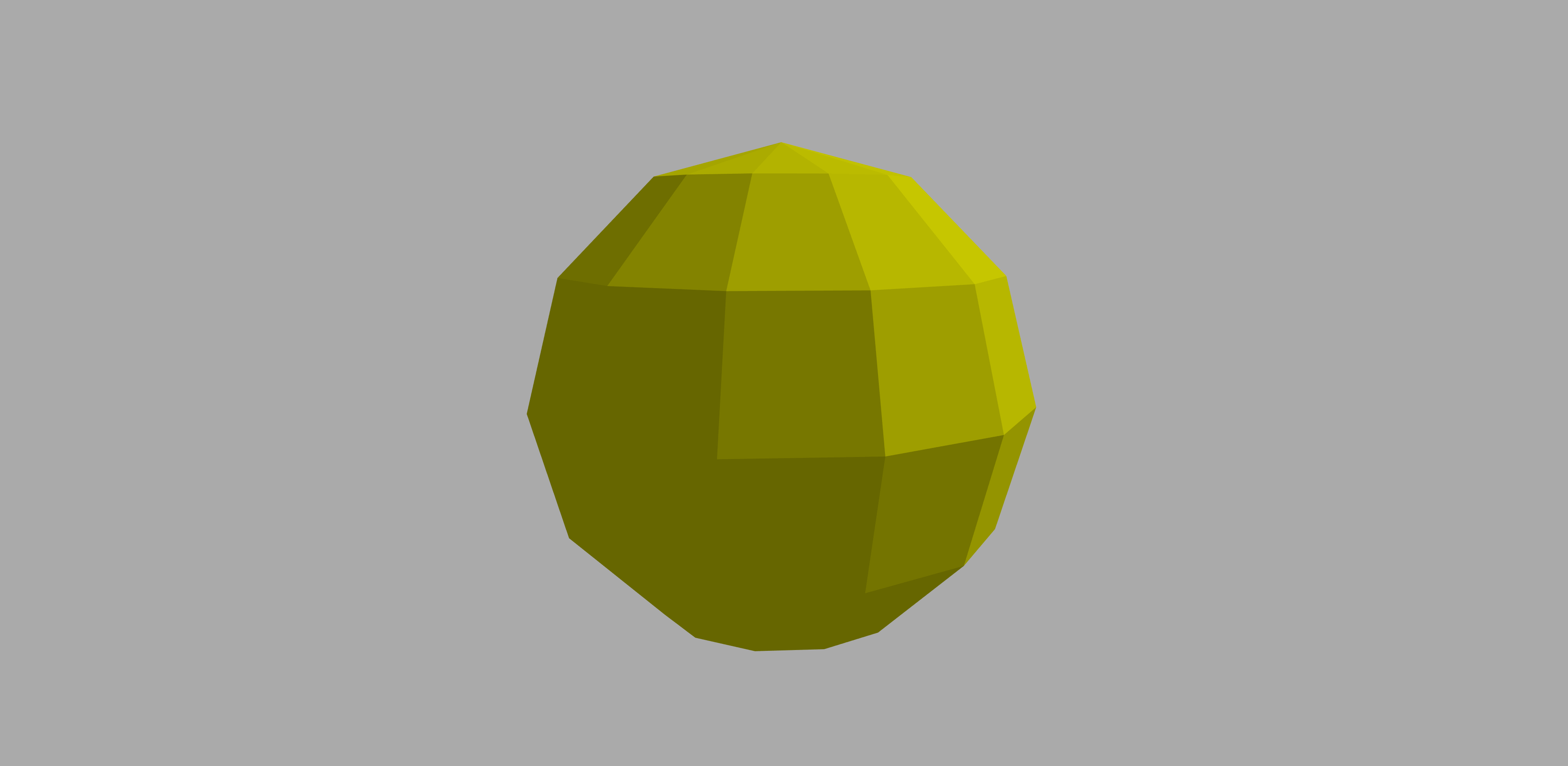
Having more vertices in a model not only helps to have a more realistic asset, but it also produces better results with the color interpolation.
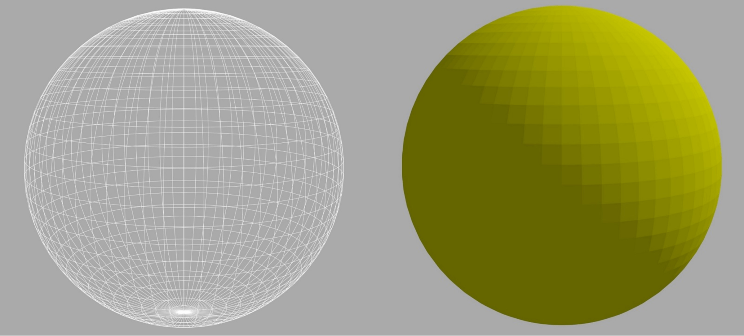
In this stage of the rendering sequence, the effect of lights in the scene can be explored in detail; for example, how the model’s materials reflect the light, can be introduced. Such calculations need to take into account the position and direction of the camera viewing the world, as well as the position and direction of the lights.

There is a whole array of different math techniques that can be employed here; some simple, some very complicated. In the above image, we can see that the process on the right produces nicer looking and more realistic results but, not surprisingly, it takes longer to work out.
It’s worth noting at this point that we’re looking at objects with a low number of vertices compared to a cutting-edge 3D game. Go back a bit in this article and look carefully at the image of Crysis: there is over a million triangles in that one scene alone. We can get a visual sense of how many triangles are being pushed around in a modern game by using Unigine Valley benchmark.
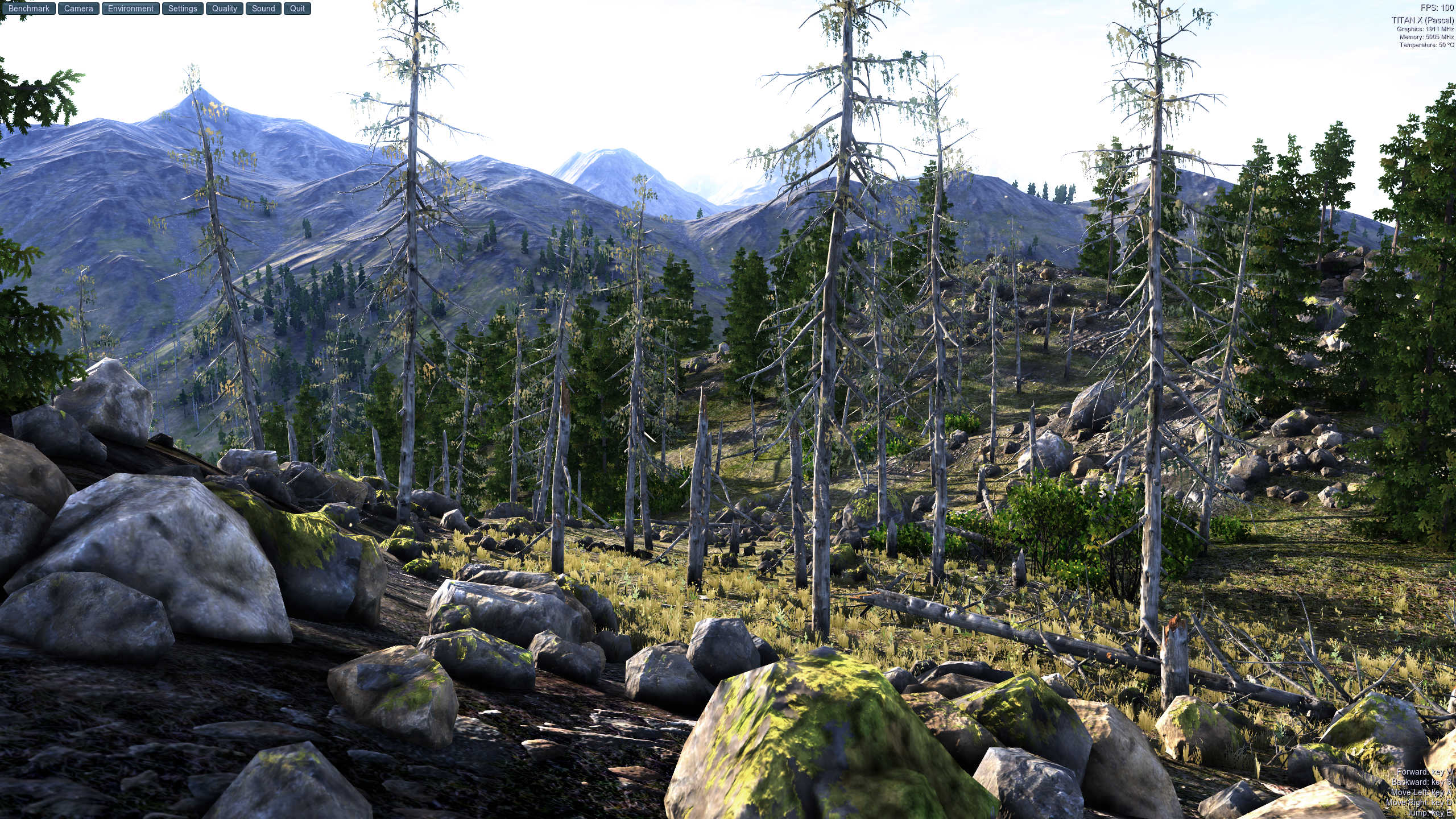
Every object in this image is modelled by vertices connected together, so they make primitives consisting of triangles. The benchmark allows us to run a wireframe mode that makes the program render the edges of each triangle with a bright white line.
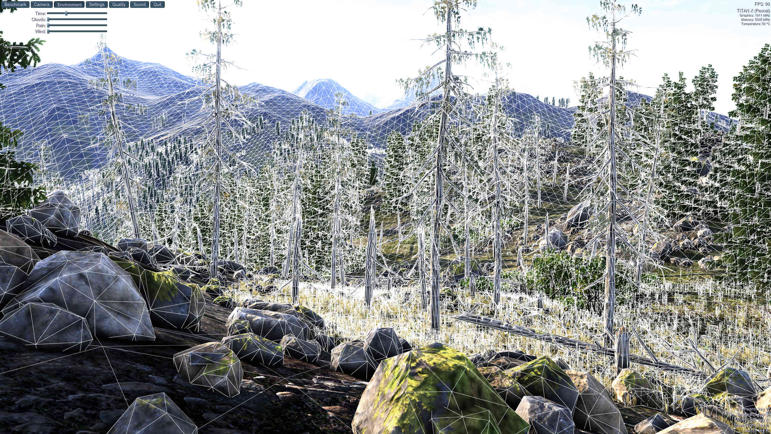
The trees, plants, rocks, ground, mountains – all of them built out of triangles, and every single one of them has been calculated for its position, direction, and color – all taking into account the position of the light source, and the position and direction of the camera. All of the changes done to the vertices has to be fed back to the game, so that it knows where everything is for the next frame to be rendered; this is done by updating the vertex buffer.
Astonishingly though, this isn’t the hard part of the rendering process and with the right hardware, it’s all finished in just a few thousandths of a second! Onto the next stage.
Losing a dimension: Rasterization
After all the vertices have been worked through and our 3D scene is finalized in terms of where everything is supposed to be, the rendering process moves onto a very significant stage. Up to now, the game has been truly 3 dimensional but the final frame isn’t – that means a sequence of changes must take place to convert the viewed world from a 3D space containing thousands of connected points into a 2D canvas of separate colored pixels. For most games, this process involves at least two steps: screen space projection and rasterization.
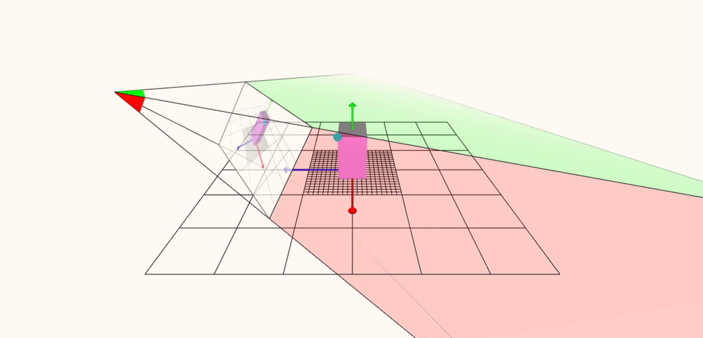
Using the web rendering tool again, we can force it to show how the world volume is initially turned into a flat image. The position of the camera, viewing the 3D scene, is at the far left; the lines extended from this point create what is called a frustum (kind of like a pyramid on its side) and everything within the frustum could potentially appear in the final frame.
A little way into the frustum is the viewport — this is essentially what the monitor will show, and a whole stack of math is used to project everything within the frustum onto the viewport, from the perspective of the camera.
Even though the graphics on the viewport appear 2D, the data within is still actually 3D and this information is then used to work out which primitives will be visible or overlap. This can be surprisingly hard to do because a primitive might cast a shadow in the game that can be seen, even if the primitive can’t.
The removing of primitives is called culling and can make a significant difference to how quickly the whole frame is rendered. Once this has all been done – sorting the visible and non-visible primitives, binning triangles that lie outside of the frustum, and so on – the last stage of 3D is closed down and the frame becomes fully 2D through rasterization.

The above image shows a very simple example of a frame containing one primitive. The grid that the frame’s pixels make is compared to the edges of the shape underneath, and where they overlap, a pixel is marked for processing. Granted the end result in the example shown doesn’t look much like the original triangle but that’s because we’re not using enough pixels.
This has resulted in a problem called aliasing, although there are plenty of ways of dealing with this. This is why changing the resolution (the total number of pixels used in the frame) of a game has such a big impact on how it looks: not only do the pixels better represent the shape of the primitives but it reduces the impact of the unwanted aliasing.
Once this part of the rendering sequence is done, it’s onto to the big one: the final coloring of all the pixels in the frame.
Bring in the lights: The pixel stage
So now we come to the most challenging of all the steps in the rendering chain. Years ago, this was nothing more than the wrapping of the model’s clothes (aka the textures) onto the objects in the world, using the information in the pixels (originally from the vertices).
The problem here is that while the textures and the frame are all 2D, the world to which they were attached has been twisted, moved, and reshaped in the vertex stage. Yet more math is employed to account for this, but the results can generate some weird problems.
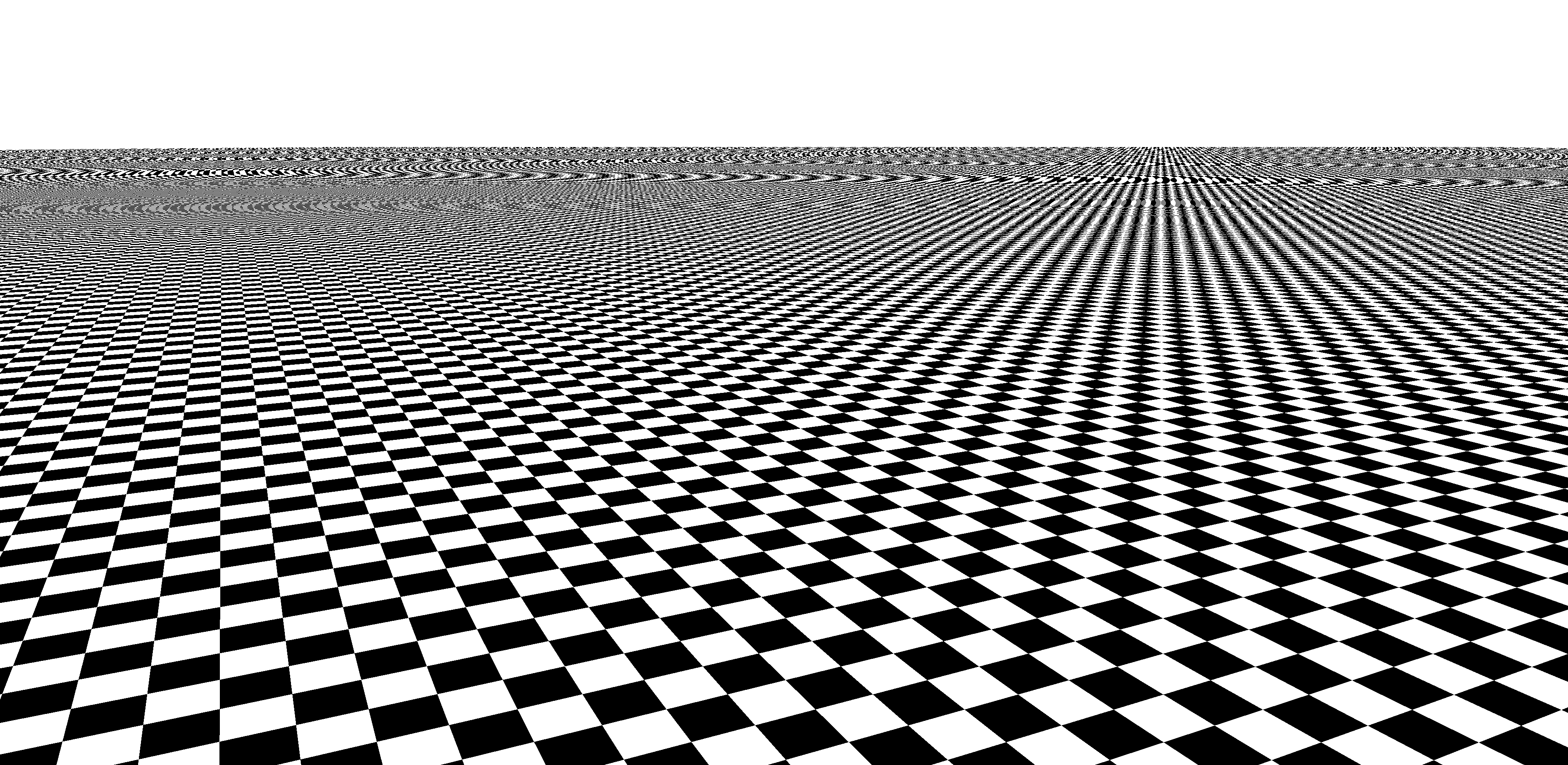
In this image, a simple checkerboard texture map is being applied to a flat surface that stretches off into the distance. The result is a jarring mess, with aliasing rearing its ugly head again.
The solution involves smaller versions of the texture maps (known as mipmaps), the repeated use of data taken from these textures (called filtering), and even more math, to bring it all together. The effect of this is quite pronounced:
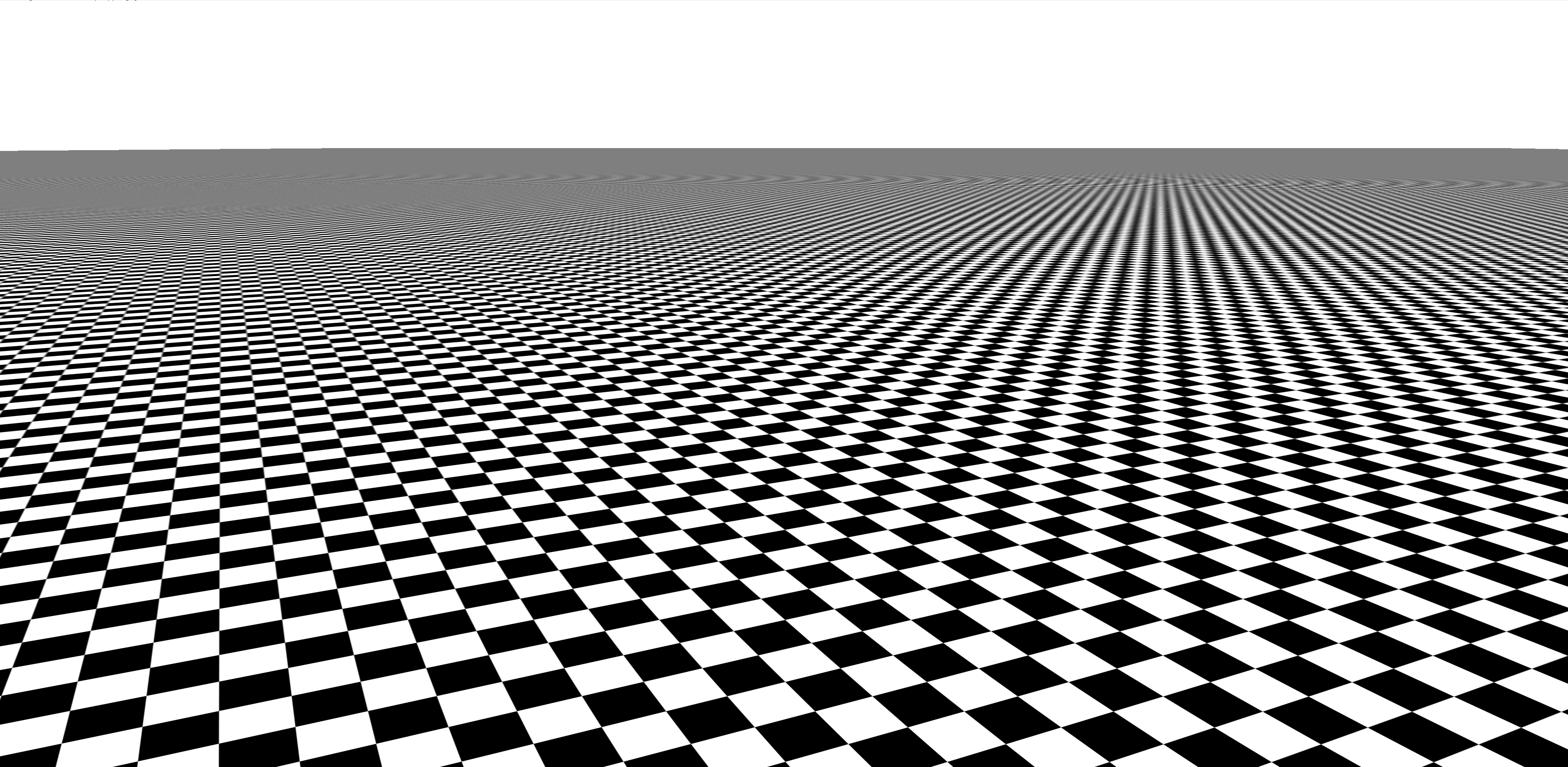
This used to be really hard work for any game to do but that’s no longer the case, because the liberal use of other visual effects, such as reflections and shadows, means that the processing of the textures just becomes a relatively small part of the pixel processing stage.
Playing games at higher resolutions also generates a higher workload in the rasterization and pixel stages of the rendering process, but has relatively little impact in the vertex stage. Although the initial coloring due to lights is done in the vertex stage, fancier lighting effects can also be employed here.
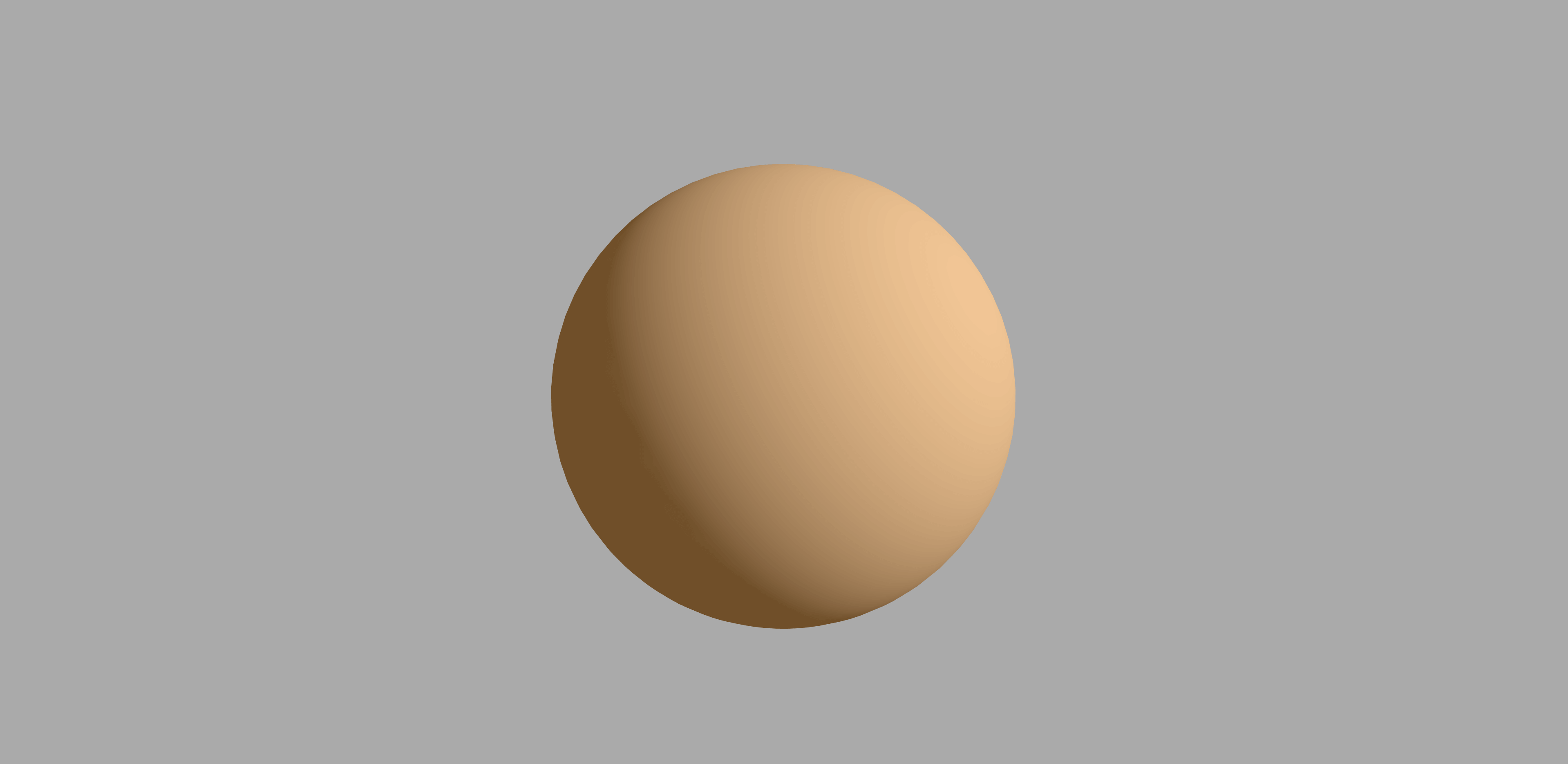
In the above image, we can no longer easily see the color changes between the triangles, giving us the impression that this is a smooth, seamless object. In this particular example, the sphere is actually made up from the same number of triangles that we saw in the green sphere earlier in this article, but the pixel coloring routine gives the impression that it is has considerably more triangles.

In lots of games, the pixel stage needs to be run a few times. For example, a mirror or lake surface reflecting the world, as it looks from the camera, needs to have the world rendered to begin with. Each run through is called a pass and one frame can easily involve 4 or more passes to produce the final image.
Sometimes the vertex stage needs to be done again, too, to redraw the world from a different perspective and use that view as part of the scene viewed by the game player. This requires the use of render targets – buffers that act as the final store for the frame but can be used as textures in another pass.
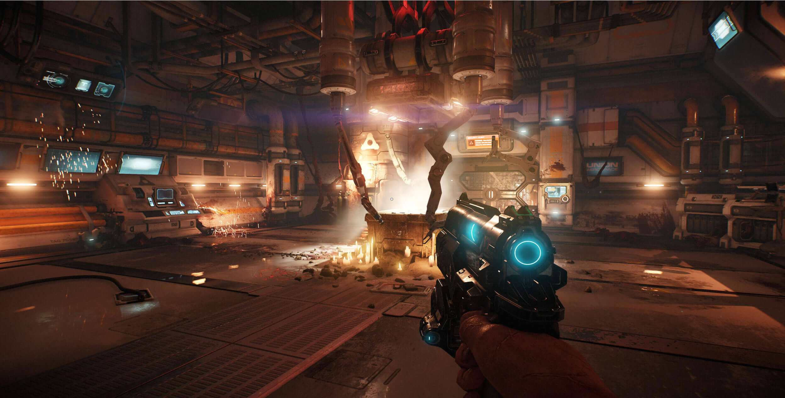
To get a deeper understanding of the potential complexity of the pixel stage, read Adrian Courrèges’ frame analysis of Doom 2016 and marvel at the incredible amount of steps required to make a single frame in that game.
All of this work on the frame needs to be saved to a buffer, whether as a finished result or a temporary store, and in general, a game will have at least two buffers on the go for the final view: one will be “work in progress” and the other is either waiting for the monitor to access it or is in the process of being displayed.
There always needs to be a frame buffer available to render into, so once they’re all full, an action needs to take place to move things along and start a fresh buffer. The last part in signing off a frame is a simple command (e.g. present) and with this, the final frame buffers are swapped about, the monitor gets the last frame rendered and the next one can be started.
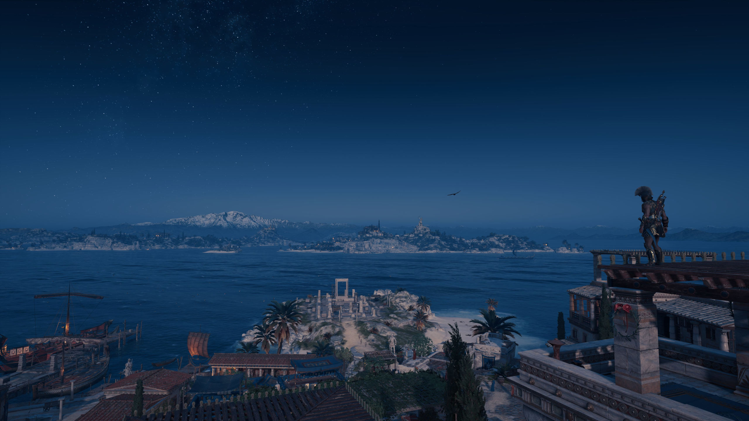
In this image, from Assassin’s Creed Odyssey, we are looking at the contents of a finished frame buffer. Think of it being like a spreadsheet, with rows and columns of cells, containing nothing more than a number. These values are sent to the monitor or TV in the form of an electric signal, and color of the screen’s pixels are altered to the required values.
Because we can’t do CSI: TechSpot with our eyes, we see a flat, continuous picture but our brains interpret it as having depth – i.e. 3D. One frame of gaming goodness, but with so much going on behind the scenes (pardon the pun), it’s worth having a look at how programmers handle it all.
Managing the process: APIs and instructions
Figuring out how to make a game perform and manage all of this work (the math, vertices, textures, lights, buffers, you name it…) is a mammoth task. Fortunately, there is help in the form of what is called an application programming interface or API for short.
APIs for rendering reduce the overall complexity by offering structures, rules, and libraries of code, that allow programmers to use simplified instructions that are independent of any hardware involved. Pick any 3D game, released in past 5 years for the PC, and it will have been created using one of three famous APIs: Direct3D, OpenGL, or Vulkan. There are others, especially in the mobile scene, but we’ll stick with these ones for this article.
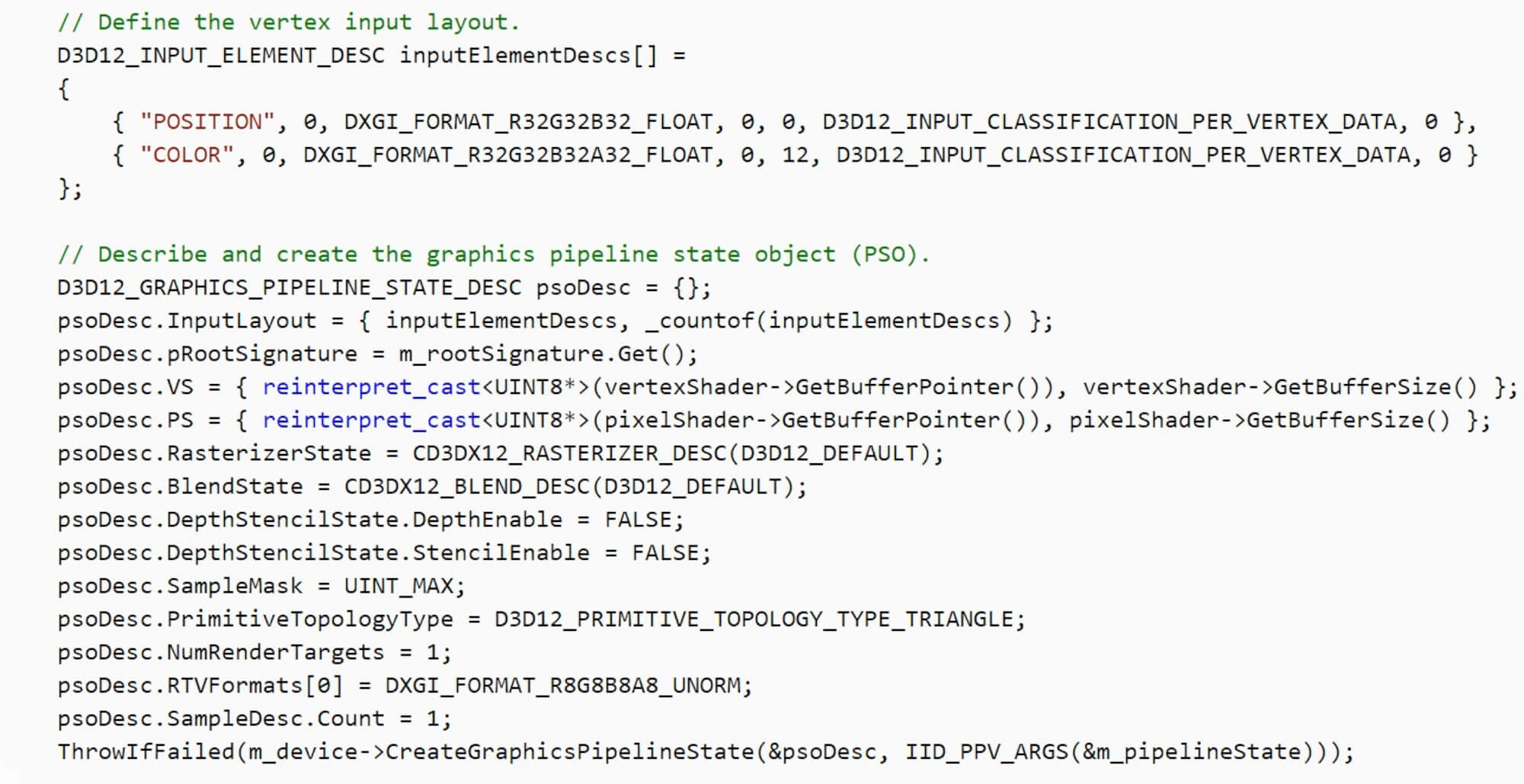
While there are differences in terms of the wording of instructions and operations (e.g. a block of code to process pixels in DirectX is called a pixel shader; in Vulkan, it’s called a fragment shader), the end result of the rendered frame isn’t, or more rather, shouldn’t be different.
Where there will be a difference comes to down to what hardware is used to do all the rendering. This is because the instructions issued using the API need to be translated for the hardware to perform – this is handled by the device’s drivers and hardware manufacturers have to dedicate lots of resources and time to ensuring the drivers do the conversion as quickly and correctly as possible.
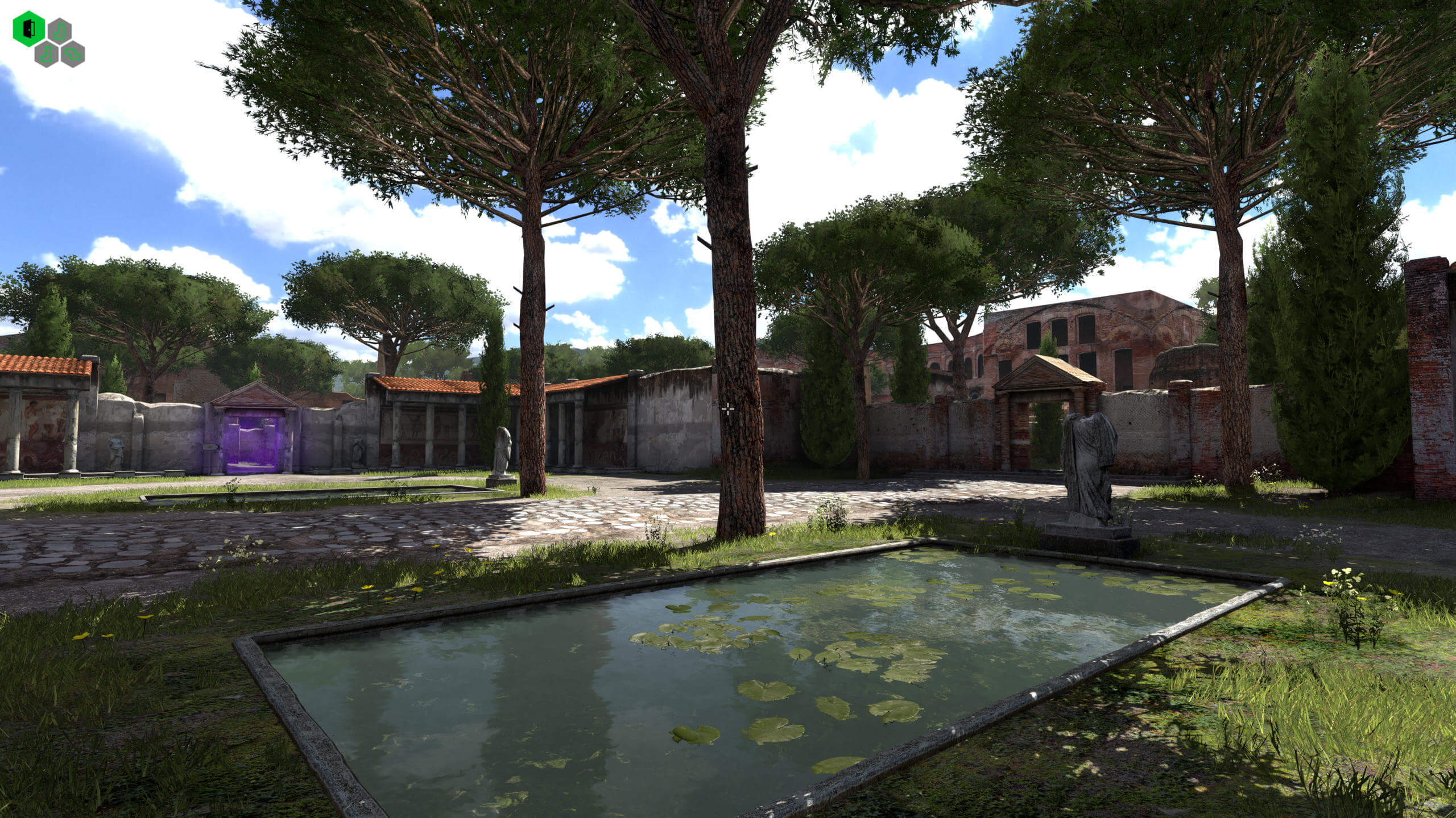
Let’s use an earlier beta version of Croteam’s 2014 game The Talos Principle to demonstrate this, as it supports the 3 APIs we’ve mentioned. To amplify the differences that the combination of drivers and interfaces can sometimes produce, we ran the standard built-in benchmark on maximum visual settings at a resolution of 1080p.
The PC used ran at default clocks and sported an Intel Core i7-9700K, Nvidia Titan X (Pascal) and 32 GB of DDR4 RAM.
- DirectX 9 = 188.4 fps average
- DirectX 11 = 202.3 fps average
- OpenGL = 87.9 fps average
- Vulkan = 189.4 fps average
A full analysis of the implications behind these figures isn’t within the aim of this article, and they certainly do not mean that one API is ‘better’ than another (this was a beta version, don’t forget), so we’ll leave matters with the remark that programming for different APIs present various challenges and, for the moment, there will always be some variation in performance.
Generally speaking, game developers will choose the API they are most experienced in working with and optimize their code on that basis. Sometimes the word engine is used to describe the rendering code, but technically an engine is the full package that handles all of the aspects in a game, not just its graphics.
Creating a complete program, from scratch, to render a 3D game is no simple thing, which is why so many games today licence full systems from other developers (e.g. Unreal Engine); you can get a sense of the scale by viewing the open source engine for Quake and browse through the gl_draw.c file – this single item contains the instructions for various rendering operations performed in the game, and represents just a small part of the whole engine.
Quake is over 25 years old, and the entire game (including all of the assets, sounds, music, etc) is 55 MB in size; for contrast, Far Cry 5 keeps just the shaders used by the game in a file that’s 62 MB in size.
Time is everything: Using the right hardware
Everything that we have described so far can be calculated and processed by the CPU of any computer system; modern x86-64 processors easily support all of the math required and have dedicated parts in them for such things. However, doing this work to render one frame involves a lot repetitive calculations and demands a significant amount of parallel processing.
CPUs aren’t ultimately designed for this, as they’re far too general by required design. Specialized chips for this kind of work are, of course GPUs (graphics processing units), and they are built to do the math needed by the likes DirectX, OpenGL, and Vulkan very quickly and hugely in parallel.
One way of demonstrating this is by using a benchmark that allows us to render a frame using a CPU and then using specialized hardware. We’ll use V-ray NEXT; this tool actually does ray-tracing rather than the rendering we’ve been looking at in this article, but much of the number crunching requires similar hardware aspects.
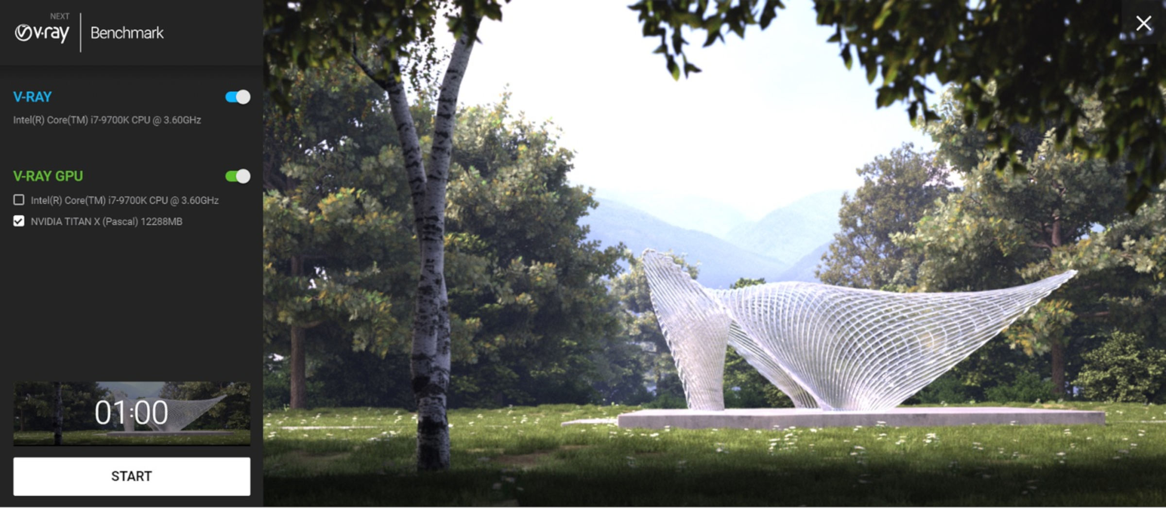
To gain a sense of the difference between what a CPU can do and what the right, custom-designed hardware can achieve, we ran the V-ray GPU benchmark in 3 modes: CPU only, GPU only, and then CPU+GPU together. The results are markedly different:
- CPU only test = 53 mpaths
- GPU only test = 251 mpaths
- CPU+GPU test = 299 mpaths
We can ignore the units of measurement in this benchmark, as a 5x difference in output is no trivial matter. But this isn’t a very game-like test, so let’s try something else and go a bit old-school with 3DMark03. Running the simple Wings of Fury test, we can force it to do all of the vertex shaders (i.e. all of the routines done to move and color triangles) using the CPU.
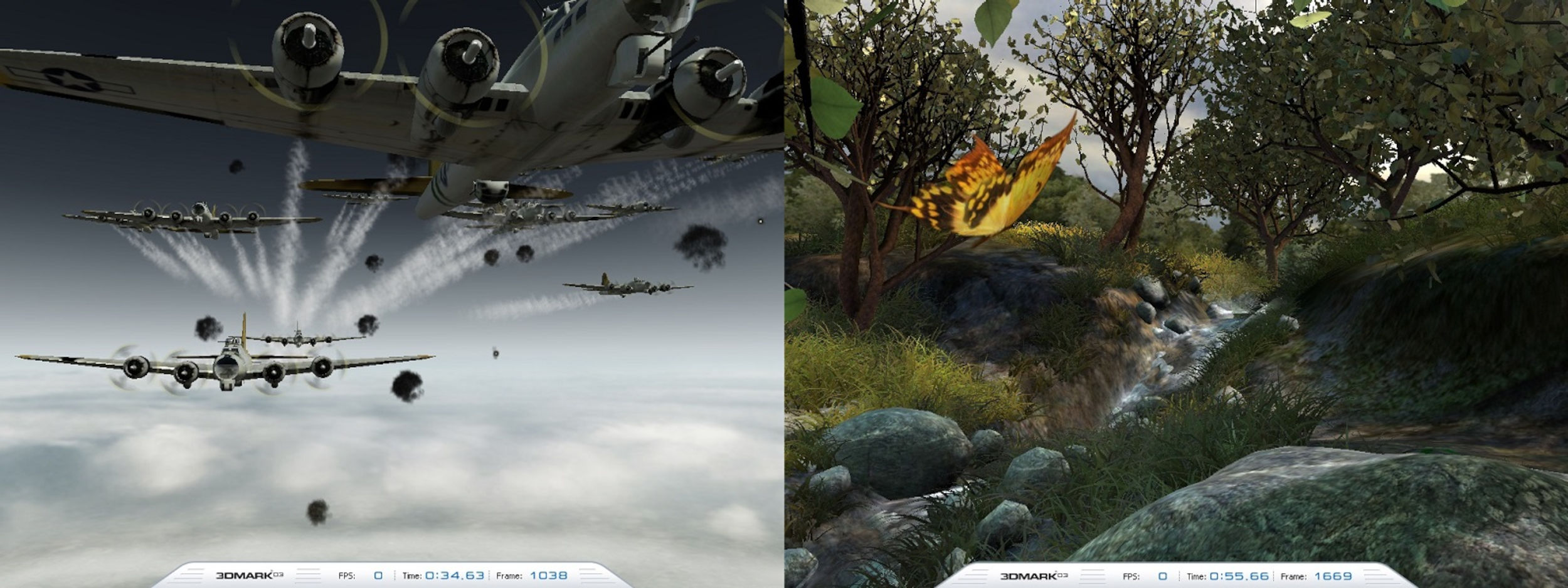
The outcome shouldn’t really come as a surprise but nevertheless, it’s far more pronounced than we saw in the V-ray test:
- CPU vertex shaders = 77 fps on average
- GPU vertex shaders = 1580 fps on average
With the CPU handling all of the vertex calculations, each frame was taking 13 milliseconds on average to be rendered and displayed; pushing that math onto the GPU drops this time right down to 0.6 milliseconds. In other words, it was more than 20 times faster.
The difference is even more remarkable if we try the most complex test, Mother Nature, in the benchmark. With CPU processed vertex shaders, the average result was a paltry 3.1 fps! Bring in the GPU and the average frame rate rises to 1388 fps: nearly 450 times quicker. Now, don’t forget that 3DMark03 is 20 years old, and the test only processed the vertices on the CPU – rasterization and the pixel stage was still done via the GPU. What would it be like if it was modern and the whole lot was done in software?
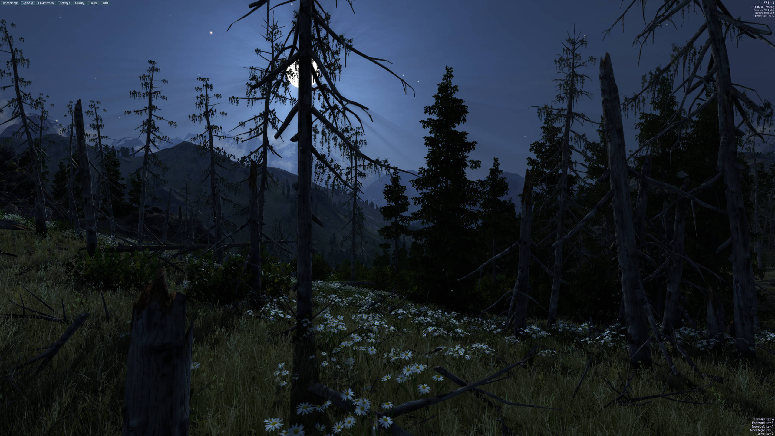
Let’s try Unigine’s Valley benchmark tool again – the graphics it processes are very much like those seen in games such as Far Cry 5; it also provides a full software-based renderer, in addition to the standard DirectX 11 GPU route. The results don’t need much of an analysis but running the lowest quality version of the DirectX 11 test on the GPU gave an average result of 196 frames per second. The software version? A couple of crashes aside, the mighty test PC ground out an average of 0.1 frames per second – almost two thousand times slower.
The reason for such a difference lies in the math and data format that 3D rendering uses. In a CPU, it is the floating point units (FPUs) within each core that perform the calculations; the test PC’s i7-9700K has 8 cores, each with two FPUs. While the units in the Titan X are different in design, they can both do the same fundamental math, on the same data format. This particular GPU has over 3500 units to do a comparable calculation and even though they’re not clocked anywhere near the same as the CPU (1.5 GHz vs 4.7 GHz), the GPU outperforms the central processor through sheer unit count.
While a Titan X isn’t a mainstream graphics card, even a budget model would outperform any CPU, which is why all 3D games and APIs are designed for dedicated, specialized hardware. Feel free to download V-ray, 3DMark, or any Unigine benchmark, and test your own system – post the results in the forum, so we can see just how well designed GPUs are for rendering graphics in games.
Some final words on our 101
This was a short run through of how one frame in a 3D game is created, from dots in space to colored pixels in a monitor.
At its most fundamental level, the whole process is nothing more than working with numbers, because that’s all computer do anyway. However, a great deal has been left out in this article, to keep it focused on the basics. You can read on with deeper dives into how computer graphics are made by completing our series and learn about: Vertex Processing, Rasterization and Ray Tracing, Texturing, Lighting and Shadows, and Anti-Aliasing.
We didn’t include any of the actual math used, such as the Euclidean linear algebra, trigonometry, and differential calculus performed by vertex and pixel shaders; we glossed over how textures are processed through statistical sampling, and left aside cool visual effects like screen space ambient occlusion, ray trace de-noising, high dynamic range imaging, or temporal anti-aliasing.
But when you next fire up a round of Call of Mario: Deathduty Battleyard, we hope that not only will you see the graphics with a new sense of wonder, but you’ll be itching to find out more.

